Tunable Lasers and Optics

Multipass optical system (MOS).
Oleg Matveev
The suggested multipass optical system shown in figures 1-26 should have two, three, four and sometimes more right angle prisms or right angle retroreflectors plus sometimes lenses and different type of mirrors. Prisms A and C shown in Fig 1-6 are identical.
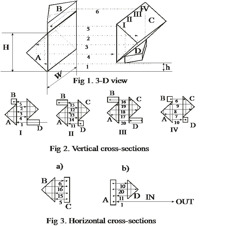
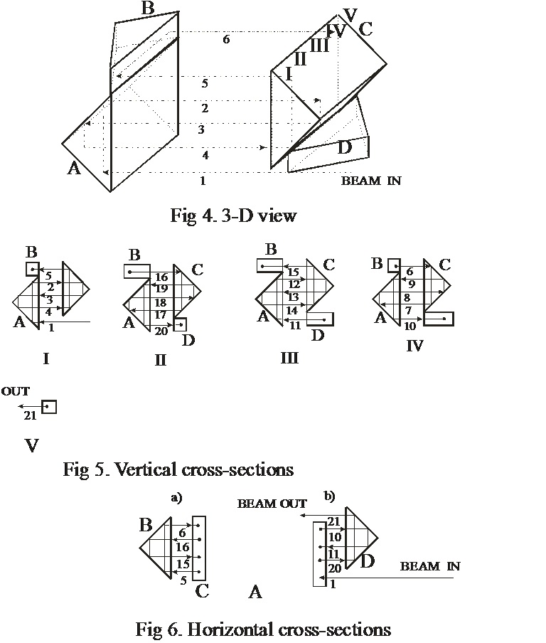
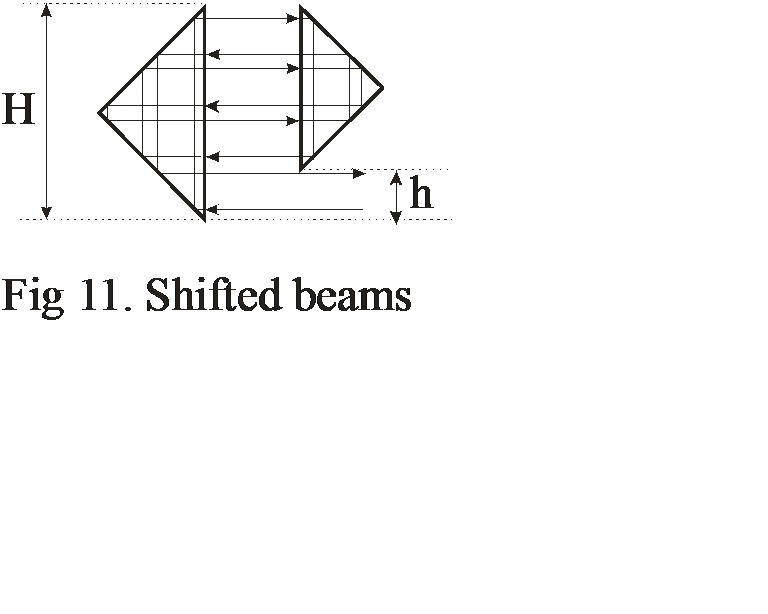
To provide optimal performance they have to be shifted vertically with height difference h, as shown in Fig1. The surface of the right angle prism which is crossed by laser beams and belonging to hypotenuse with size H we will call H-surface. In order to get maximum number of beams to be passed through the medium between prisms the beam has to fill the whole area with sizes H and W between prisms C and D, also the size of the beam has to be with height approximately equal h and width also h, or with h being diameter of the beam. It is preferable (however not necessarily) that the ratio of H/h is integer and in some cases even number. In a first embodiment, shown in Fig 1-3, the width of H-surfaces difference of prisms B and D also has to be equal h or nh (where n is integer). The widths W of prisms A, B, C should be equal. In the second embodiment shown in Figures 4,5,6 W of all prisms are equal and prisms B and D are shifted horizontally at the distance h as shown in Fig 4. The difference between prisms of the MOS shown inFig 1-3 and 4-6 is the number of passes between prisms and output beam directions. The prisms shown in Fig 1-3 can provide total 40 number passes. In Fig 2 only 20 first passes are shown for four vertical I, II, III, IV cross sections of prisms. All other 20 passes go into opposite directions. The beam #21 goes exactly where beam #20, but has opposite direction. Beam #40 goes exactly where beam #1 was directed but also in opposite direction. For example, if laser beam has size 4 x 4mm, in order to provide 40 passes between prisms A, B, C, D shown in Fig 1, the size of H- surface for prisms A and C has to be 16 x 16 mm, and for prisms B and D 4 x 16 and 4 x 12 mm correspondingly. In Fig 3 horizontal cross-sections are shown a) from the top and b) from the bottom of prisms assembly shown in Fig.1
Interesting to note that the MOS shown in Fig.1-3, which has a beam matrix 4x5, can prowide maximim number of ray passes equal 2[(H+h)W/h], i.e. 2[4x5]=40. However, generally speaking, maximum number of passes is possible only if beam matrixes are odd-odd, or odd-even. For example, the MOS with beam matrix 3x2 can provide 12 passes, 3x3 -18, 3x4 - 24, but 4x4 only 4 passes, 3x5 -30, 4x5 - 40, 5x5 - 50, 5x6 - 60, 6x6 - 6, 3x7 - 42, 4x7 - 56, 5x7 - 70, 6x7 - 84, 7x7 = 98, 8x7 - 112, but 8x8 only 8 passes.
Advantages of suggested multipass systems is the fact that size H does not have to be equal to the size W, i.e. providing the opportunity to illuminate the areas with very different heights, widths and also any, even very small, distance between H-surfaces of the prisms. In this case as seen in Fig 6 the output beam #21 goes in the same direction however separately from the input beam.
To simplify the pictures in Fig 1 and 4 only six first passes are shown. And in Fig. 2 only first 20. Actual number of passes, which can be achieved is 40 for the case depicted in Fig 1-3 and 21 in Fig 4-6. In Fig 5 and 6 vertical and horizontal cross sections of prism assembly are shown similar to Fig 2. and Fig. 3.
As shown in Fig. 7 instead of prisms right angle retroreflectors can be used; or the whole device can be designed to have partially prisms and partially retroreflectors.
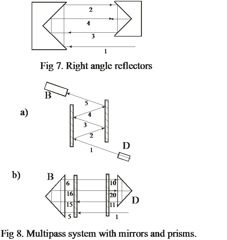
As shown in Fig.8 instead of prisms A and C plane or spherical, cylindrical and other type of mirrors can be used. Prisms B and D in this case have the same functions and can have the same sizes as shown inFig 1 andFig4. Fig 8 a) in this case shows view from the front and b) from the top of prisms-mirrors assembly. However in this case laser beams will not fill the whole area between mirrors, where voids and areas with double crossings will occur.
Important advantage of suggested multipass system is the ability to provide focused in one point several beams what is important, for example, for Raman and mutiphoton (absorption, fluorescence and ionization etc.) spectroscopy of liquids and gases. InFig 9 2D (two dimensional) multipass optical system with focusing lenses (which can be spherical, cylindrical or with specially designed surfaces to eliminate aberrations) is shown and in Fig 10 3D system is depicted.
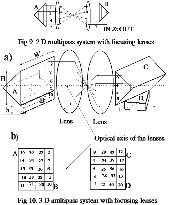
This ability to focus the beam occur as a result of rotational with respect to optical axes C2 symmetry for 2D and 3D multipass systems shown in Fig 9 and 10. For simplicity in the picture Fig 10 a) only first 10 crosses of the H surface are shown; and in the matrixes in the bottom of Fig. 10 b) only 40 first numbers of laser beam crosses of H surfaces is shown. Actual number of crosses is 80 and the number of beams passes is 40. After first 40 every next beam cross of H surface goes exactly in the opposite direction. On matrixes in Fig 10 b) by dashed lines positions of right angle corners are shown for prisms A, B, C, and D.
The suggested multipass optical system can be used for any applications where lasers illuminate transparent mediums. In particular the suggested MOS can be used for optical delay lines, light pulse stretching system; in Raman, CARS, absorption, laser enhanced ionization, resonance and multiphoton ionization, fluorescence, ionization, thermal lens, magnetic rotation of polarization plane spectroscopy and analysis; also for laser chemical reactors, for laser isotope separation; laser generators and amplifiers, for fast rotating Q switches of lasers; Raman lasers and Raman frequency shifters; laser radiation frequency doublers; atoms and molecules cooling; laser induced breakdown of air, gases, liquids and solids; for different type of mutiphoton spectroscopy and analysis; for resonance ionization image detectors and resonance fluorescence imaging monochromators; for pico- and femtosecond spectroscopy and lasers, pulse stretchers, gyroscopes; as an element for photoionization sources in gas chromatography, mass spectrometry, ion mobility spectrometers, capillary and other type of electrophoresis, high performance liquid chromatography.
Also it can be used for photofragmentation and after that fluorescence (or/and Raman, emission and chemiluminescence etc) analysis of many substances. One of the most important group of substances to be analyzed might be explosives. In this case the energy of laser for photofragmentation might be 10 -1000 times less than in a single beam spectrometers, i.e. the whole system can be designed to be very portable.
The disclosed MOS can also be used in compact generators of X-rays by inverse Compton scattering. Similar system is described in a paper by A.J. Rollason, et al , Nuclear instruments and Methods in Physical Research A 526, (2004) 560-571. Another important application can be direct and/or holographic information (including diffraction gratings, lenses et ) recording and reading in transparent medium.
If the width of the beam is less or equal h/2 as shown in Fig 11 the returned beam can be shifted and is not exactly collinear with the original one. I.e. in this case the suggested system can provide several number of passes, however they are not going to be completely overlapped.
In comparison with known multipass systems the suggested system has several advantages.
- Possible number of passes for non focused beams equal 2[(H+h)W/h]; known systems provide at best 2-3 times less . In case of focused beams this number can be much higher.
- It can provide even and homogeneous filling by laser light the whole illuminated area between prisms.
- Since all beams are parallel to each other and the system in many cases provide C2 rotational symmetry there is a possibility to focus all beams into one point.
- There is an opportunity to illuminate the areas with almost any desirable heights, widths and length.
- The design is simple and inexpensive.
- A MOS with prisms allows to achieve much higher threshold of optical damage by laser radiation in comparison with a MOS with mirrors. The MOS design with prism require to use antireflection (AR) coatings on the surfaces of optical elements which are less expensive and can withstand much higher laser power in comparison with high reflection coatings used for MOS with spherical and flat mirrors. 7.
- For the same level of optical damage threshold right angle prisms with AR can have normally broader wavelength range than high reflectivity mirrors.
- 3D version, the same as 2D bersion of MOS with 90 degrees prism can have practically the same rather homogenious illuminated area between prisms for any distance between them.
The suggested MOS was simulated using optical design software Optilab5.22 made by a company Science Lab Software ,6731 Lemon Leaf Drive,Carlsbad,CA 92009
http://www.optics-lab.com. The results of the simulations are shown in figures 12 -25. It need to be emphasize that despite of the fact that in Figures 12,13, 16 -20,22 all simulation had been performed in two dimensional (2D) variant all of them can also be done in 3D embodiment like it is done in Figures 14,15, 21, 25 A and B.
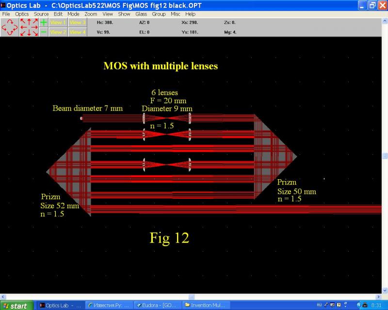
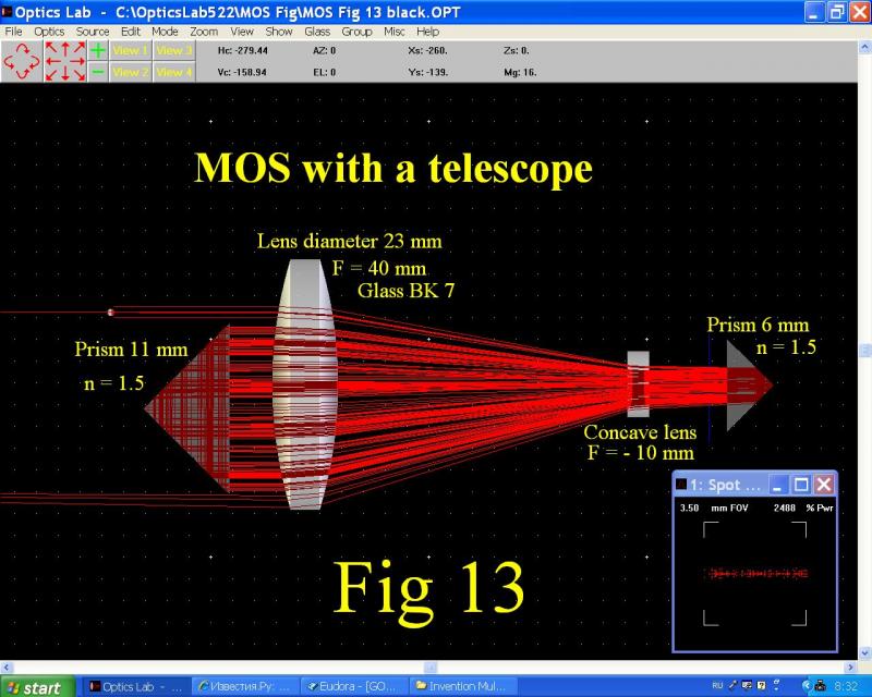
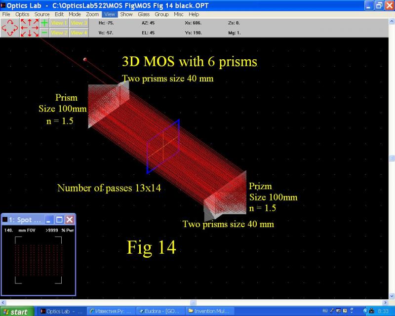
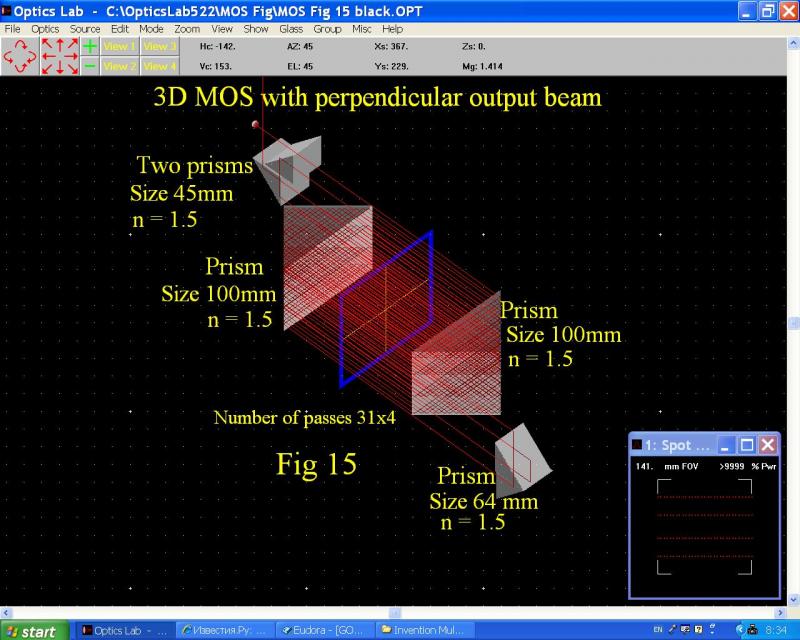
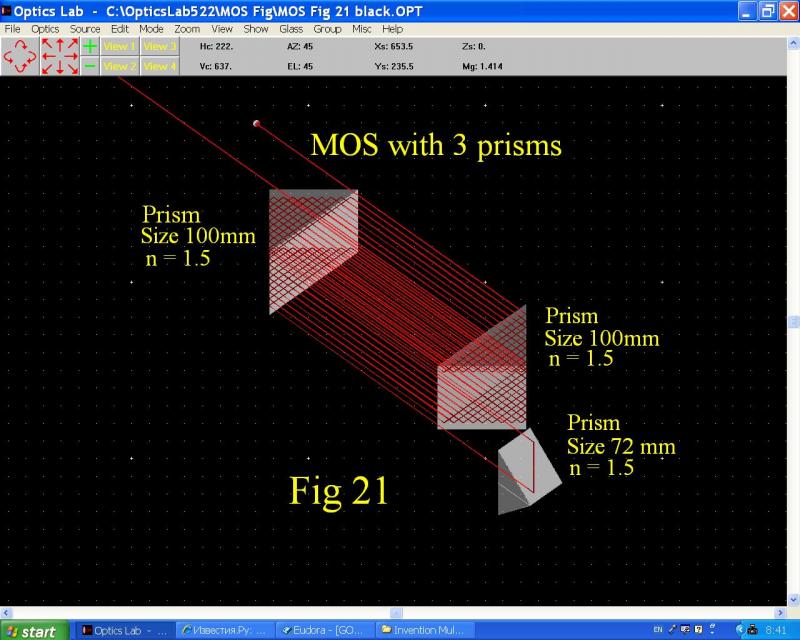
In Figures 14,15 and 21 the MOSs with 6, 5 and 3 prisms are shown, with number of laser beams passes 182, 124 and 38. The MOS shown in fig 14 is similar with MOS depicted in figures 4-6. Interestingly, prisms B and F in Fig 15 can be shifted providing the output beam perpendicular to input beam. In Fig 12 the MOS is shown where only three out of seven beams had been focused, to show that the suggested MOS is flexible enough to provide different type of focusing modes. This type of MOS when all beams are focused can be used, for example, for laser radiation Raman shifter, frequency doubling or for optical parametric oscillators. The Fig 13 depicts a MOS with a telescope, which can provide squeezed beams between concave lens and small prism. One of the interesting application of such MOS might be for lasers amplifiers, Raman lasers etc.
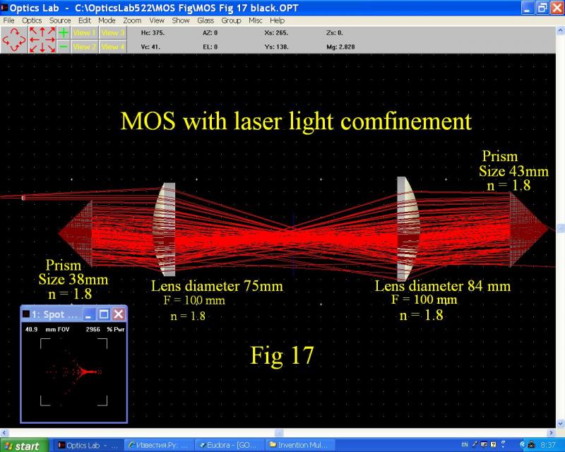
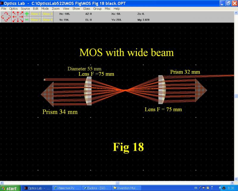
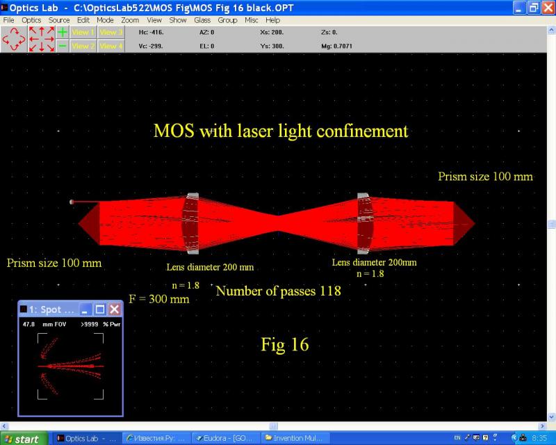
When two focusing lenses are inserted between prisms as shown in Figures 16 -20,22 the beam can be focused into one point ( see Fig18, 19, 20, 22) and also provide confinement (Figures 16 and 17) of laser light between prisms similar like it is done with mirrors ( see for example
A.J. Rollason, et al , Nuclear instruments and Methods in Physical Research A 526, (2004) 560-571.)
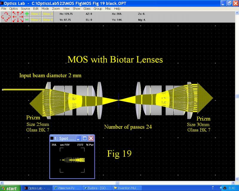
As shown in Fig. 19 when instead of prisms well corrected for distortions objectives are inserted ( in our case Biotar objective) several beams can be focused into one very small spot with size 0.195 x 0.04 mm.
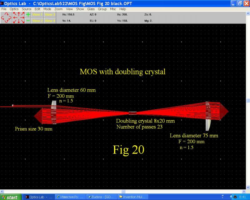
In Fig. 20 another interesting application of suggested MOS is shown, when laser frequency doubling crystal with angle frequency tuning properties is inserted in the focus between lenses. The process of second harmonic (SH) generation for different laser radiation frequencies can be done without rotation of the crystal. Using predetermined prisms and lenses the optical assembly shown in Fig.20 can provide different doubled laser frequencies without crystal rotation. In the case simulated in Fig. 20 doubling crystal has 23 beams passing the crystal with different incidence angles. Since MOS with hundreds of beams can be designed by choosing appropriate lenses hundreds of different frequencies continuously or discretely positioned can appear in the output beam. For example, if in the design shown in Fig 20 KDP crystal is chosen, which is cut o + o → e for SH generation with θ ≈ 530 , tunable laser radiation having 23 discretely positioned lines without crystal rotation can appear in the spectral range approximately 620 – 830 nm. By choosing long focusing lenses with focal length F > 200 mm this spectral range can become more narrow. The doubled radiation lines will be closer to each other tend to be continuously tuned for certain focal length of lenses.
Interesting that simplified version of the MOS shown in figures 1-3 with 3 prisms can provide two sheets of laser rays as shown in Fig.21. There every sheet has 18 beams positioned approximatelly 60 mm from each other.
To eliminate rather large number of reflecting surfaces the whole system in 2D and 3D variants can be designed with combined prisms and lenses as shown if Fig.22.
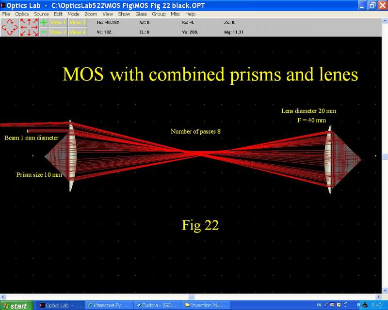
As seen similarly to MOS with mirrors in our case only two surfaces can reflect laser light, however, there is big advantage, they have to be coated not by reflecting but by AR coatings, which is not so expensive and have much higher optical damage threshold.
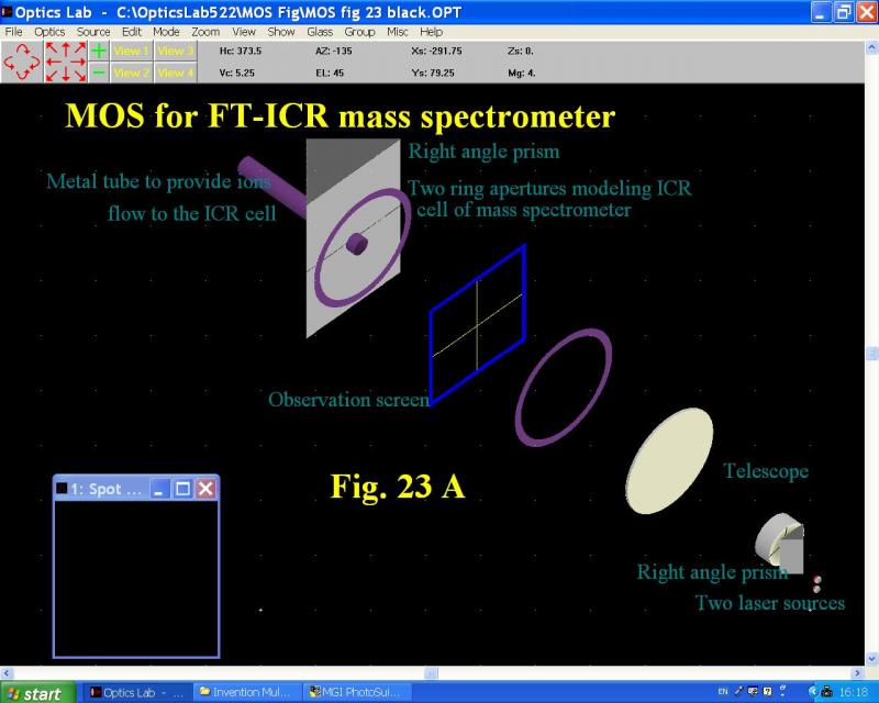
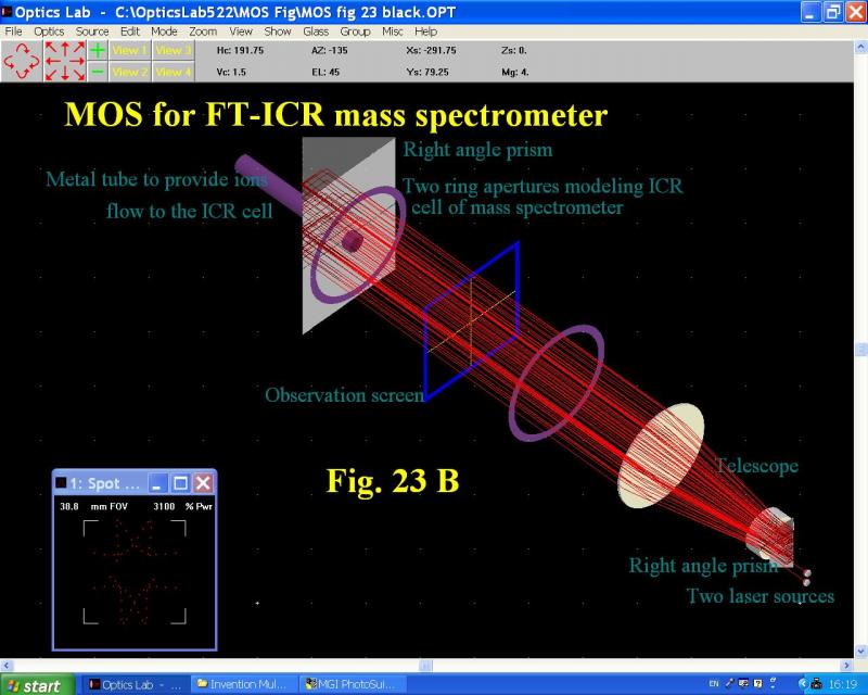
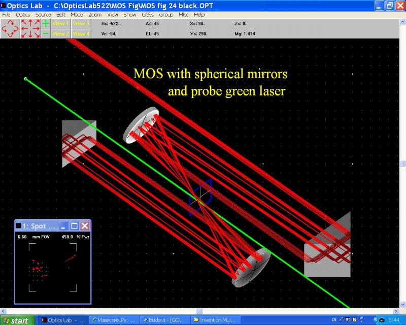
As we mentioned the suggested MOS can be used in mass spectrometry. In Fig 23 A, 23 b and 24 the design is shown, which can be used for ICR FT mass-spectrometers. As can be seen the MOS in this case can provide almost 32 passes for two laser sources. The most important feature of this MOS is its ability to illuminate areas around metal tube inserted into prism to provide ions flow into ICR cell. In Fig 24 another type of the design is shown with focused beams. The ions flow can come collinearly with probe green laser beam.
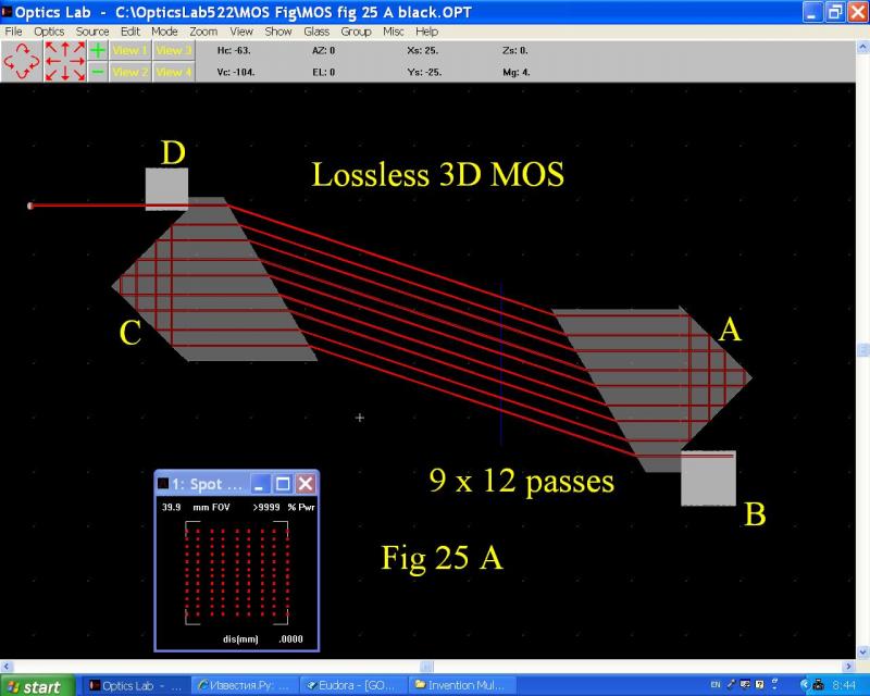
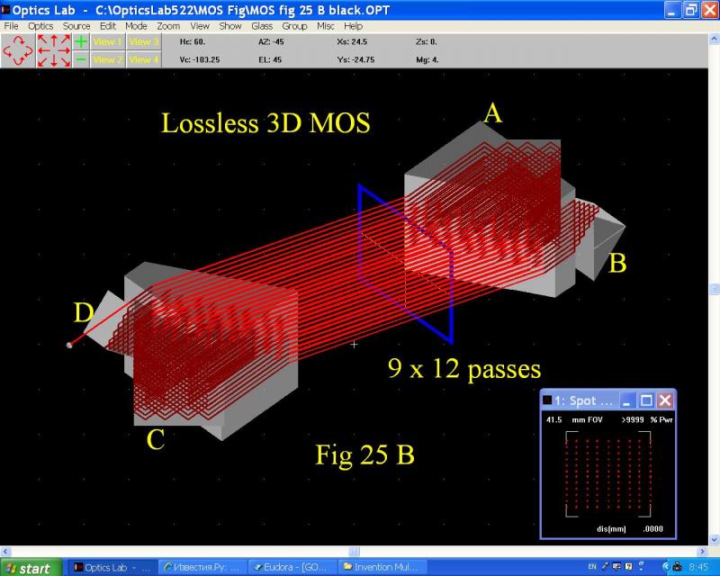
In fig 25 A and 25 B a MOS is shown which when using polarized beam can provide practically lossless passage through the media. This can be achieved when prism A and C are designed in a way that all beams do not have reflections from the surfaces tilted at Brewster angle.
In Fig 26 compact Raman laser spectrometer is shown with MOS designed from standard right angle prisms having h-surfaces heights 14.1 (from the right) and 17 mm (from the left) and two lenses. CW 532 nm laser with 60 mW power and beam diameter 2 mm was used to illuminate a sample. The MOS provided 8 passes of laser beam. Simple fiber optic Ocean Optics SD 2000 spectrometer was used to detect Raman spectrum. For this design the Raman signal was increased almost five times.
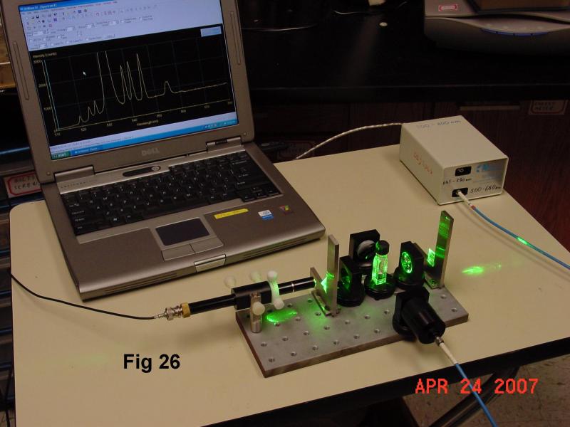
Clear Stokes and anti-Ststokes Raman lines of carbon tetrachloride are seen on the computer screen.
In Figures 27 and 28 a MOS designed on a teflon coated optical bench with powerful Nd:YAG laseer are shown.
References
1. J. U. White, "Long optical paths of large aperture," J. Opt. Soc. Am. 32, 285- (1942)
2. P.G. Lethbridge, A. J. Stace, Design considerations for the construction of a reflecting symmetric multipass cell for use in laser molecular-beam experiments, Rev. Sci. Instrum. 58(12), 1987, p. 2238-2243.
3. Artyom L. Vitushkin and Leonid F. Vitushkin. Design of a multipass optical cell based on
the use of shifted corner cubes and right-angle prisms APPLIED OPTICS, Vol. 37, No. 1p.165. 1 January 1998.
4. A.J. Rollason, X. Fang, D.E. D.E.Dugdale, Multipass Optical Cavity for Inverse Compton interactions, Nuclear instruments and Methods in Physical Research, A 526, (2004) 560-571.
5. US Patent # 3437954, 1969, Optical Delay Line Devises.
6. US Patent # 5291265, 1994, Off-Axis Cavity Absorption Cell.
|
|
|
|